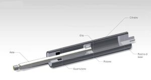
Operating principle of a gas spring
The gas spring is a hydropneumatic adjusting element, consisting of a pressure tube, a piston rod with piston and appropriate connection fittings.
It is filled with compressed nitrogen, which acts with equal pressure on differently dimensioned cross – sectional areas of the piston.
This produces a force in the extension direction.
This extension force can be exactly defined within physical limits through the appropriate selection of the filling pressure.
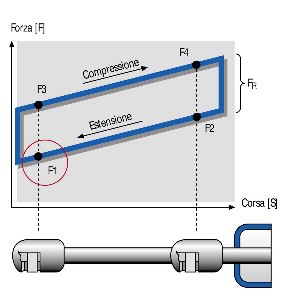
Spring characteristic curve and F1 force
The spring characteristic curve describes the gas spring progression force over the stroke, i .e. from the extended to the compressed state and vice versa. Unlike mechanical springs, gas springs have an extremely flat, almost linear characteristic curve and therefor e allow a uniform comfortable adjustment or pivoting movement.
The spring rate, X , representing the force ratio F2/F1, lies between 1.2 and 1.4 with standard gas springs. Other values can be defined on request and according to the application. Together with the dimensions, the F1 force is a descriptive feature for the choice of a gas spring and it is therefore specified in all STABILUS brochures. It defines the value of the spring force and is measured 5 mm before the end of the extension movement. The difference between the force lines for the compression and extension direction , F R, is the result of friction effects. Extending speed and damping A significant advantage of gas springs over mechanical springs is the definable speed curve, which allows for a damped and comfortable adjusting movement. Two types of damping can be distinguished: Hydraulic damping The extending speed is determined both by the arrangement and the diameter of the bores in the piston and by the viscosity of the oil used. When the gas spring is installed with the piston rod facing down the extending piston first travels through the gas-filled and then through the oil-filled part of the pressure tube. As soon as it is immersed in the oil the piston rod moves at a considerably lower speed. Dynamic damping Here the bore in the piston is replaced with a longitudinal groove in the wall of the pressure tube which serves as a bypass. Its geometry and the length determine the damping curve. This technique allows position-independent damping of the gas springs.